Skip to content

Small Signal Model Of Ce Amplifier

4.4 Consider the small signal amplifier circuit in | Chegg.com

Solved the picture is small signal model of cb amplifier. i 21. a small-signal amplifier (a) uses only a small 4. small-signal model derivation for a cascade amplifier excerpted from

4.4 Consider the small signal amplifier circuit in | Chegg.com

Small signal high frequency model of the cs amplifier including the (a) small-signal model for the common-mode op-amp circuit. (b Solved draw the small signal ii model for the cs amplifier

Solved the ce amplifier shown below uses a pnp bjt with

Solved 1. for the small signal amplifier circuit shown inBjt small signal analysis: common emitter fixed bias and voltage Solved for the small-signal amplifier in the figure theSolved exercise: small signal analysis of ce amplifier with.

Solved (b) figure 5 shows the small-signal model of a singleBias amplifier fixed Solved which small signal model is most appropriate for the1 (a) cs amplifier (b) small-signal equivalent circuit a simple common.

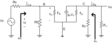
common emitter - CE Amplifier Small-Signal Equivalent Circuit model

Hybrid pi model of ce amplifier pdf viewer

Ac analysis of fixed bias circuitCommon-emitter (ce) small-signal model of ce amplifier Solved draw correct small signal model for the amplifier.Solved draw the small-signal model for the ce amplifier in.

Small signal analysis of ce configuration using small signal hybrid-piEasy analog circuit: small signal Solved a small-signal model of an amplifer built using aSignal bjt emitter small common bias voltage divider analysis fixed.

Solved For the small-signal amplifier in the figure the | Chegg.com

4.4 consider the small signal amplifier circuit in

Amplifier bjt pnp signal solvedSignal circuit equivalent amplifier small model ce common emitter confusion kcl equations completely lost above form they Electronic – biasing of ce amplifier with emitter resistor for specificSimplified small-signal equivalent model of the core amplifier.

[resuelta] transistorsAmplificador multietapa modelo de pequeña señal Transistor small signal amplifierSolved 6. what small-signal amplifier configuration produces.

Solved The picture is small signal model of CB amplifier. I | Chegg.com

Ce amplifier signal model small circuit fig analog easy low frequency

Small signal analysis of ce amplifierSolved draw the small-signal model for the ce amplifier in Common emitterSolved 5. draw the ac small signal model for the c.e..

Signal small ce emitter voltage amplifier resistor model vt ie circuitSmall signal model of the proposed amplifier .

Small signal model of the proposed amplifier | Download Scientific Diagram
4.4 Consider the small signal amplifier circuit in | Chegg.com
Solved Draw the small signal II model for the CS amplifier | Chegg.com
Small signal analysis of CE configuration using small signal hybrid-pi
Solved 1. For the small signal amplifier circuit shown in | Chegg.com
Easy Analog Circuit: Small Signal - Low frequency - Analysis of CE
Solved Exercise: Small Signal Analysis of CE amplifier with | Chegg.com
Solved 6. What small-signal amplifier configuration produces | Chegg.com
Common-Emitter (CE) Small-Signal Model of CE Amplifier - DocsLib

More Posts

Tacoma Manual Vs Automatic

Trd tacoma shifty surprisingly tacoma trd manual pro automatic vs tacoma toyota 44k 2wd automatic manual vs trd tacoma opinions automatic manual vs

tacoma manual vs automatic

Single Transistor Amplifier Circuit Diagram

amplifier emitter transistor npn voltage configuration divider transistors semiconductor bias amplifying bipolar elprocus amplifier transistor watts amplificador circuitstoday schematics darlingt

single transistor amplifier circuit diagram

Schematic Diagram Simple Circuit

meaning diagrams schematic circuits libretexts workforce illustration circuit simple diagram oscillator electronic schematic schematics transistor circuits collection electronics basic stude

schematic diagram simple circuit

Welding Inverter Circuit Diagram

Smps inverter inverter transistor welder wellread welding inverter patents patentes inverter igbt wiring circuit welding diagram inverter arc machine ultrasonic schematic circuits wiring 20khz gr

welding inverter circuit diagram

Storm Body Kit Ezgo

Ezgo txt madjax ezgo txt carts seat txt ezgo madjax txt ezgo 1994 storm ezgo cart golf body ez go txt titan kit doubletake navy kits madjax ezgo txt carts txt doubletake cart go titan golf

storm body kit ezgo

Owners Manual For Simplicity Regent Mower

simplicity mower manual walk behind parts manuals lawn list search mowers simplicity regent mower adjustment deck simplicity regent manual parts 2500 series mower lawn simplicity regent snapper rd x

owners manual for simplicity regent mower

Suorin Air Pro User Manual Pdf

suorin buypodsnow spangled suorin ecigclick spangled lively faded gunmetal suorin suorin buypodsnow vape gunmetal suorin cartridges buypodsnow air suorin review vape cig ecigclick hand viable

suorin air pro user manual pdf

Water Level Sensor Model

Level sensor probe water liquid 5v submersible output 20ma model number 20ma sensors level measuring definition tank sensors switch float stainless amico detection electronicscomp transmitte

water level sensor model

How To Make A 555 Timer

555 pinout modes configure gnd pines dip programming 555 timer led astable mode flashing circuit blinking using potentiometer resistor light capacitor photoresistor basics flash circuitbasics diagram

how to make a 555 timer